
SORA 2.5
SPECIFIC OPERATIONS RISK ASSESSMENT
All UAS operators are required to conduct a SORA risk assessment for their intended operations if the operations cannot be adapted to Open category rules or conditions of a predefined risk assessment or a Standard Scenario (STS)
Commission Implementing Regulation (EU) 2019/947 article 11 deals with the specific category risk assessment procedure and is described in more detail in the Easy Access Rules document published by European Union Aviation Safety Agency EASA.
The basis of the SORA procedure is to guarantee the same level of safety for the operation as in manned aviation. The SORA procedure consists of 10 different steps, which are described below.
The European Union Aviation Safety Agency (EASA) published Executive Decision 2025/018/R amending the Acceptable Means of Compliance (AMC) / Guidance Material (GM) under Commission Implementing Regulation (EU) 2019/947 to incorporate SORA 2.5.
Applicants for Operational Autnorisations in Cyprus shall use SORA 2.5, from 01/03/2026 onwards, when conducting their risk assessment.
BUT before proceeding with the SORA evaluation, operators must perform a PRE-APPLICATION EVALUATION (shown below). If none of the cases apply in this evaluation then the operator can begin the SORA process.
0. Pre-Application Evaluation
The operator must answer the following questions. If the answer to ALL of them is NO then the SORA process can start:
The operation falls under the ‘Open’ category? YES / NO
The operation is covered by a STS or by a PDRA? YES / NO
The operation falls under the ‘certified’ category? YES / NO
The operation is subject to a specific NO-GO from the Civil Aviation Authority? YES / NO
The Drone employed in the operations is recognised Harmless by the Civil Aviation Authority? YES / NO
The SORA process phases (GUIDANCE)
As part of the SORA, it is critical to review the steps and to validate the assumptions and derivations made throughout this process. The SORA process has a natural break point after Step#9 (see Figure below), from which the SORA process can be split into two phases.
i. Phase 1 focuses on the derivation of safety requirements and proposed means of compliance, and
ii. Phase 2 focuses on compliance with the derived safety from Phase 1.
The phases ensure there is a review of the first phase outputs for the applicant to determine if any adjustments to the proposed operation are required before undertaking the second phase. This approach should minimise unnecessary iterations in the operational procedures, remote crew requirements, and system(s) design in the proposed operations and mitigations.
An additional benefit of the phases is that it provides an engagement point with the competent authority. This is intended to support reaching a preliminary agreement that Phase 1 has been undertaken correctly, and that the derived requirements and proposed means of compliance for Phase 2 are appropriate.
 Phase 1:
The purpose of Phase 1 is to derive all relevant safety requirements based on the proposed operation which should result in a document suite that sufficiently describes the proposed operation(s). This should include the relevant information, safety claims and derived requirements of Step #1 to Step #9. The applicant should collect explanations, but not the entire justification, of the means by which the applicant will demonstrate compliance with any safety claims and derived in Phase 1. This can assist both the applicant and competent authority in ensuring any means of compliance proposed is valid and will result in satisfying the safety claims.
The results of this phase may be the basis for a pre-application evaluation by the competent authority. The competent authority may or may not be able to provide a formal agreement until the submission and review of final compliance evidence (covered in Phase 2).
It is recommended that the applicant contacts the competent authority as early as possible in order to present the available information and reach a common initial understanding and in-principle agreement on the safety claims, in particular the final GRC, residual ARC, and SAIL.
Phase 2:
Phase 2 occurs after the completion of Step #9. This phase is a final set of iterations to complete the SORA process. This should result in a SORA Comprehensive Safety Portfolio (CSP), which collects the work done in all previous steps of the SORA into a comprehensive, justified document suite showing compliance with the SORA provisions. The SORA Compliance Matrix can be downloaded ΕΔΩ.
If completed correctly, the CSP should provide all the necessary claims, arguments and evidence to support the assessment and approval of the proposed operation.
The SORA process:
1. Documentation of the proposed operation(s)
Step #1 provides an opportunity for an applicant to collect and present contextual information on the proposed operation and the intended safety claims made during Phase 1 of the SORA process. The applicant should:
(a) Compile operational, technical, and organisational information. This may include:
i. Various maps, figures, diagrams and other information detailing the operational volume, ground risk buffers, adjacent area, and adjacent airspace to facilitate the determination of:
A. the intrinsic ground risk class (i.e., population density maps, land use information),
B. the initial air risk class (i.e., airspace use information, aerodromes, and airspace charts), and
C. the adjacent areas.
ii. Information on the operational, technical, and organisational elements of:
A. the operation and functions during flight, including intended flight profiles, states, and modes that provide safety throughout the nominal, contingency, and emergency phases of flight,
B. any ground and air risk mitigations (strategic and tactical) used to reduce the intrinsic ground risk or initial air risk.
(b) A description of the contingency volume and ground risk buffers, and how they were determined.
(c) The applicant may use Chapter A3 of Annex A to AMC1 to Article 11to assist in understanding the type of data that needs to be presented and any other information that supports the risk assessment to the authority.
2. Determination of the Intrinsic UAS Ground Risk Class (GRC)
In this step the UAS operator is required to assess the intrinsic ground risk of the operational volume and ground risk buffer. No ground risk mitigations will be applied at this step, this may be completed in Step #3.
To calculate and document the Intrinsic Ground Risk class, the applicant should:
(a) Identify the maximum characteristic dimension and the maximum speed of the UA.
(b) Identify the iGRC footprint:
i. Identify the flight geography;
ii. calculate the contingency volume;
iii. calculate the initial ground risk buffer (the final ground risk buffer calculation will be completed in Step #8);
(c) Identify the highest population density within the iGRC footprint.
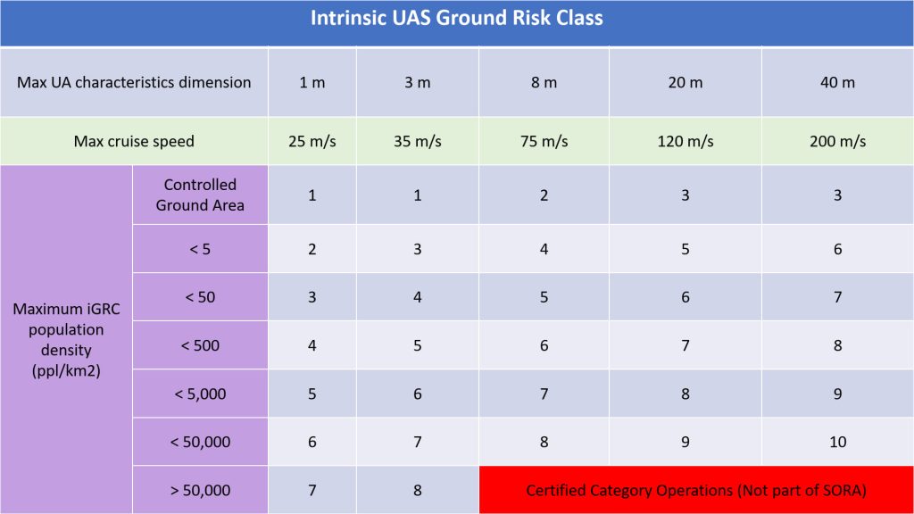
(d) Identify the iGRC of the footprint using the Table below for fixed wing, rotorcraft – helicopter, rotorcraft– gyroplane, VTOL capable aircraft (including multirotor):
Note:
1.A UA with a take off mass less than or equal to 250g and having a maximum speed less than or equal to 19 m/s is considered to have an iGRC of 1 regardless of population density.
2. A UA expected to not penetrate a standard dwelling will get a -1 GRC reduction in Step 3 from the M1(A) sheltering mitigation when not overflying large open assemblies of people, see SORA Annex B for additional details.
For maximum UA characteristic dimension examples refer to definition I.141 of Annex I to AMC 1 to Article 11.
For Maximum speed:
i. The maximum speed is conservatively defined as the maximum possible commanded airspeed of the UA, as defined by the designer,
ii. This is not the mission specific maximum commanded airspeed of the UA as reducing the mission airspeed may not necessarily reduce the impact area. Mitigations that limit airspeed below the maximum speed value during an impact can be accounted for in Annex
B to AMC 1 Article 11, part of Step #3.
For the identification and derivation of the iGRC:
(a) The iGRC is found at the intersection of the applicable maximum population density and the left most column matching both criteria, the maximum UA characteristic dimension and the maximum speed in Table above.
(b) The applicant can provide substantiation to the competent authority for a different iGRC. See Annex F17 Appendix A for further guidance.
(c) Operations that do not have a corresponding iGRC (i.e., grey cells on the table) are outside the scope of the SORA methodology. Applicants falling in these categories should consider the certified category.
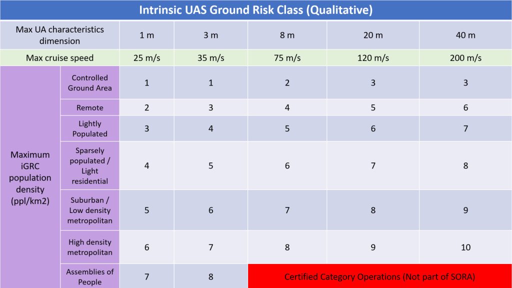
(d) In the event that population density values are not available or not accurate the UAS operator may use qualitative descriptors for the iGRC table, the following approximations can be used as guidance:
Regarding the area of operation the applicant should:
Define the area at risk when conducting the operation, which is defined as the intrinsic GRC footprint. This is composed of the operational volume plus the ground risk buffer. The operational volume is composed of the flight geography and the contingency volume. (refer
To determine the operational volume the applicant should consider the position keeping capabilities of the UAS in 4D space (latitude, longitude, height and time). In particular, the accuracy of the navigation solution, the flight technical error of the UAS, the path definition error (e.g., map error) and latencies should be accounted for in this determination. The iGRC footprint is used to determine the population density. It is expected that for many flight operations, the iGRC footprint may cover segments with different population densities.
The segment with the highest population density should be used when determining the iGRC.
3. Final Ground Risk Class (GRC) determination
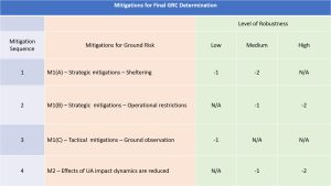
Step #3 is an optional step:
(a) The mitigations used to modify the iGRC have a direct effect on the safety objectives associated with an operation, and therefore it is important to ensure their robustness. This has particular relevance for technical mitigations (e.g., parachute).
(b) The Final GRC determination is based on the availability and correct application of the mitigations to the operation. The table above provides a list of potential mitigations and the associated relative correction factor. All mitigations must be applied in numeric sequence to perform the assessment. Annex B to AMC1 Article 11 provides additional details on the robustness of each mitigation. Competent authorities may define or accept additional mitigations and the relative correction factors.
(c) A quantitative approach to mitigations allows a reduction in the iGRC by 1 point if the mitigation reduces the at-risk population to the next lowest iGRC population band. This is in most cases approximately a factor of 10 (90% reduction) compared to the risk that is assessed before the mitigation means are applied. Such quantitative criteria may be used to validate the risk reduction that is claimed when applying Annex B to AMC1 Article 11 .
(d) In rare situations, iGRC reductions larger than the ones shown in the above table may be possible. Refer to Annex B to AMC1 Article 11 for further guidance.
(e) When applying all the M1 mitigations, the final GRC cannot be reduced to a value lower than the lowest value in the applicable column in the table shown in step#2.. This is because it is not possible to reduce the number of people at risk below that of a controlled ground area.
(f) In case the mitigation influences the descent behaviour of the UA, for example by using a parachute, the ground risk buffer size should be redefined using the updated assumptions including the effects of the mitigation means.
(g) Additional information can be found in Chapter A.3 if Annex A to AMC1 Article 11, for guidance on presenting the data supplementing the risk assessment to the competent authority.
The air risk process overview
The SORA uses the operational airspace defined in the ConOps as the baseline to evaluate the intrinsic risk of a mid-air collision, and by determining the air risk category (ARC). The ARC may be modified/lowered by applying strategic and tactical mitigation means. The application of strategic mitigations may lower the ARC level. An example of strategic mitigations to reduce the risk of a collision may be by operating during certain time periods or within certain boundaries. After applying the strategic mitigations, any residual risk of a mid-air collision is addressed by means of tactical mitigations.
Tactical mitigations take the form of detect and avoid (DAA) systems or alternate means, such as ADS-B, FLARM, U-space services or operational procedures. Depending on the residual risk of a mid-air collision, the tactical mitigation performance requirements (TMPR) may vary.
As part of the SORA process, the UAS operator should cooperate with the relevant service provider for the airspace (e.g. the ANSP or U-space service provider (USSP)) and obtain the necessary authorisations. Additionally, generic local authorisations or local procedures allowing access to a certain portion of controlled airspace may be used if available.
Irrespective of the results of the risk assessment, the UAS operator should pay particular attention to all the features that may increase the detectability of the UA in the airspace. Therefore, technical solutions that improve the electronic conspicuousness or detectability of the UAS are recommended.
4. Determination of the initial air risk class (ARC)
The competent authority (in Finland Traficom), ANSP, or U-space service provider, may elect to directly map the airspace collision risks using airspace characterisation studies. These maps would directly show the initial ARC for a particular volume of airspace. If the competent authority, ANSP, or U-space service provides an air collision risk map (static or dynamic), the applicant should use that service to determine the initial ARC, and go directly to step #5 ‘Application of strategic mitigations’ to reduce the initial ARC.
The ARC flowchart below can be used to determine the initial air risk class:

The ARC is a qualitative classification of the rate at which a UAS would encounter a manned aircraft in typical generalised civil airspace. The ARC is an initial assignment of the aggregated collision risk for the airspace, before mitigations are applied. The actual collision risk of a specific local operational volume could be much different, and can be addressed with the application of strategic mitigations to reduce the ARC (this step is optional).
Although the static generalised risk put forward by the ARC is conservative, there may be situations where that conservative assessment may not suffice. It is important for both the competent authority and the UAS operator to take great care to understand the operational volume and under which circumstances the definitions in the ARC flowchart picture above could be invalidated. In some situations, the competent authority may raise the operational volume ARC to a level which is greater than that advocated by the ARC flowchart picture. The ANSP should be consulted to ensure that the assumptions related to the operational volume are accurate.
- ARC-a is generally defined as airspace where the risk of a collision between a UAS and a manned aircraft is acceptable without the addition of any tactical mitigation.
- ARC-b, ARC-c, ARC-d generally define volumes of airspace with increasing risk of a collision between a UAS and a manned aircraft.
During the UAS operation, the operational volume may span many different airspace environments. The applicant needs to perform an air risk assessment for the entire range of the operational volume.
5. Application of strategic mitigations to determine the residual ARC (optional)
As stated before, the ARC is a generalised qualitative classification of the rate at which a UAS would encounter a manned aircraft in the specific airspace environment. However, it is recognised that the UAS operational volume may have a different collision risk from the one that the generalised initial ARC assigned. If an applicant considers that the generalised initial ARC assigned is too high for the condition in the local operational volume, then they should refer to Annex C of the EASA Easy Access Rules AMC to Article 11 for the ARC reduction process. If the applicant considers that the generalised initial ARC assignment is correct for the condition in the local operational volume, then that ARC becomes the residual ARC.
6. Tactical Mitigation Performance Requirements (TMPR) and robustness levels
Tactical mitigations are applied to mitigate any residual risk of a mid-air collision that is needed to achieve the applicable airspace safety objective. Tactical mitigations will take the form of either ‘see and avoid’ (i.e. operations under VLOS), or they may require a system which provides an alternate means of achieving the applicable airspace safety objective (operation using a DAA, or multiple DAA systems). Annex D of the EASA Easy Access Rules AMC to Article 11 provides the method for applying tactical mitigations.
Operations under VLOS/EVLOS
VLOS is considered to be an acceptable tactical mitigation for collision risk for all ARC levels. Notwithstanding the above, the UAS operator is advised to consider additional means to increase the situational awareness with regard to air traffic operating in the vicinity of the operational volume.
Operational UAS flights under VLOS do not need to meet the TMPR, nor the TMPR robustness requirements. In the case of multiple segments of the flight, those segments conducted under VLOS do not have to meet the TMPR, nor the TMPR robustness requirements, whereas those conducted under BVLOS do need to meet the TMPR and the TMPR robustness requirements.
In general, all VLOS requirements are applicable to EVLOS. EVLOS may have additional requirements over and above those of VLOS. The EVLOS verification and communication latency between the remote pilot and the observers should be less than 15 seconds.
Notwithstanding the above, the applicant should have a documented VLOS de-confliction scheme, in which the applicant explains which methods will be used for detection, and defines the associated criteria applied for the decision to avoid incoming traffic. If the remote pilot relies on detection by observers, the use of phraseology will have to be described as well.
For VLOS operations, it is assumed that an observer is not able to detect traffic beyond 2 NM. However, the 2 NM range is not a fixed value and it may largely depend on the atmospheric conditions, aircraft size, geometry, closing rate, etc.. Therefore, the UAS operator may have to adjust the operation and/or the procedures accordingly.
Operations under a DAA system — TMPR
For operations other than VLOS, the applicant will use the residual ARC and the table below to determine the TMPR.

High TMPR (ARC-d): This is airspace where either the manned aircraft encounter rate is high, and/or the available strategic mitigations are low. Therefore, the resulting residual collision risk is high, and the TMPR is also high. In this airspace, the UAS may be operating in integrated airspace and will have to comply with the operating rules and procedures applicable to that airspace, without reducing the existing capacity, decreasing safety, negatively impacting current operations with manned aircraft, or increasing the risk to airspace users or persons and property on the ground. This is no different from the requirements for the integration of comparable new and novel technologies in manned aviation. The performance levels of those tactical mitigations and/or the required variety of tactical mitigations are generally higher than for the other ARCs. If operations in this airspace are conducted more routinely, the competent authority is expected to require the UAS operator to comply with the recognised DAA system standards (e.g. those developed by RTCA SC-228).
Medium TMPR (ARC-c): A medium TMPR will be required for operations in airspace where the chance of encountering manned aircraft is reasonable, and/or the strategic mitigations available are medium. Operations with a medium TMPR will likely be supported by the systems currently used in aviation to aid the remote pilot in the detection of other manned aircraft, or by systems designed to support aviation that are built to a corresponding level of robustness. Traffic avoidance manoeuvres could be more advanced than for a low TMPR.
Low TMPR (ARC-b): A low TMPR will be required for operations in airspace where the probability of encountering another manned aircraft is low, but not negligible, and/or where strategic mitigations address most of the risk, and the resulting residual collision risk is low. Operations with a low TMPR are supported by technology that is designed to aid the remote pilot in detecting other traffic, but which may be built to lower standards. For example, for operations below 120 m, the traffic avoidance manoeuvres are expected to mostly be based on a rapid descent to an altitude where manned aircraft are not expected to ever operate.
The traffic detection requirement for low TMPR is to detect at least 50% of all aircraft in the detection volume, e.g. by relying on one or more of the following:
- Use of web-based real time aircraft tracking services
- Use Low Cost ADS-B In or FLARM aircraft trackers
- Monitoring aeronautical radio communications
No TMPR requirement (ARC-a):This is airspace where the manned aircraft encounter rate is expected to be extremely low, and therefore there is no requirement for a TMPR. It is generally defined as airspace where the risk of a collision between a UAS and a manned aircraft is acceptable without the addition of any tactical mitigation. Operations in segregated airspace (D/R area) are also considered as ARC-a operations.
Annex D of the EASA Easy Access Rules AMC to Article 11 provides more detailed description of the Tactical Mitigation Performance Requirements.
Consideration of additional airspace/operational requirements
Modifications to the initial and subsequent approvals may be required by the competent authority or the ANSP as safety and operational issues arise.
The UAS operator and the competent authority need to be cognisant that the ARCs are a generalised qualitative classification of the collision risk. Local circumstances could invalidate the aircraft density assumptions of the SORA, for example, due to special events.
Operations in controlled airspace, an airport/heliport environment or a Mode-C Veil/transponder mandatory zone (TMZ) will likely require prior approval from the ANSP.
7. Final assignment of specific assurance and integrity level (SAIL) and Perational Safety Objectives (OSO)
The SAIL parameter consolidates the ground and air risk analyses, and drives the required activities. The SAIL represents the level of confidence that the UAS operation will remain under control. After determining the final GRC and the residual ARC, it is then possible to derive the SAIL associated with the proposed ConOps.
The SAIL is not quantitative, but instead corresponds to:
- the OSO to be complied with
- the description of the activities that might support compliance with those OSO’s
- the evidence that indicates that the objectives have been satisfied.
The SAIL assigned to a particular ConOps is determined using the table below:

8. Determination of Containment Requirements
The containment provisions ensure that the target level of safety can be met for both ground and air risk in the adjacent area. The containment provisions are derived from the difference between the final ground risk level in the operational volume plus ground risk buffer, and the final ground risk level in the adjacent area. There are three possible levels of robustness for containment: low, medium and high; each with a set of safety requirement described in Annex E to AMC1 Article 11.
If the UA has a take-off weight of less than 250g apply low containment with no required operational limits for the population in the adjacent area and go to Step #9. However when conducting a multiple simultaneous operation (MSO), the competent authority may require tohave additional considerations related to safety and security.
Otherwise:
Determine the size and population characteristics of the adjacent area:
i. Calculate the size of the adjacent area for the operation. The lateral outer limit of the adjacent area is calculated from the operational volume as the distance flown in 3 minutes at maximum speed of the UA:
A. if the distance is less than 5 km, use 5 km,
B. if the distance is between 5 km and 35 km, use the distance calculated,
C. if the distance is more than 35 km, use 35 km.
ii. Calculate the average population density between the outer limit of the ground risk buffer and the outer limit of the adjacent area.
iii. Assess the presence of outdoor assemblies of people during the time when the flight takes place within 1 km of the outer limit of the operational volume.
Determine a set of operational limits appropriate for intended operation using the columns in the tables below:
i. Choose an operational limit for the acceptable average population density in the established adjacent area.
ii. Choose an operational limit for the acceptable size of assemblies of people within 1km surrounding the operational volume.
Use the 6 tables provided in SORA 2.5 to identify the required containment robustness level for the chosen operational limits, the characteristic dimension of the UA and the SAIL of the operation. As an example please see the tables below:
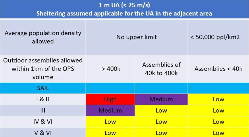
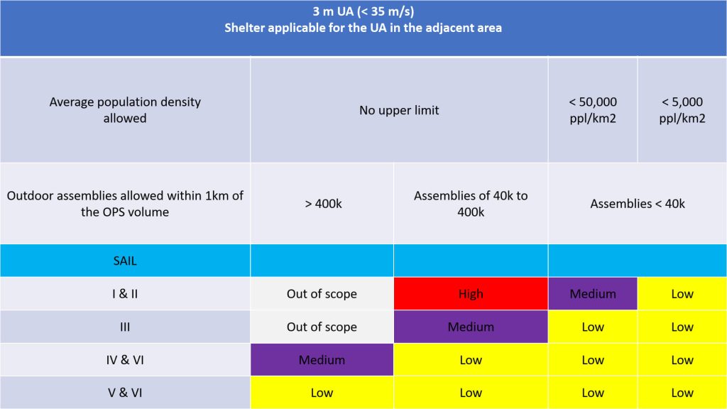
(a) When using the table above to identify the required containment robustness level of the operation:
i. Select the correct table based on the maximum characteristic dimension of the UA used in Step 2.
A. For a 3m UA determine whether sheltering can be applied in the adjacent area
B. If sheltering applies for a UA greater than 3m, the operator can use Annex F26 to apply the credit and determine the appropriate containment provisions;
ii. Identify the correct row based on the SAIL found in Step 7;
iii. identify the appropriate column to derive the containment level of robustness based on the adjacent area population density.
iv. If the results are ‘out of scope’, the operation cannot be conducted in the specific category. In this case, adjusting the location of the operation or an increase of the SAIL of the operation could be considered.
(b) Example: An operation uses a SAIL III 2.5 m drone with a maximum speed of 30 m/s, sheltering is applicable, the outer limit of the adjacent area is 5.4 km from the boundary of the operational volume. An assessment of the adjacent area shows no large assemblies of people within 1 km and the area is mostly over rural and suburban areas, expecting an average population density between 1k-4k people/km^2. This results in low containment provisions. If the UAS operator decides to use a UA with low containment, the operator should document operational limitations for the low containment SAIL III UA:
i. No assemblies of people > 40k people within 1 km of the operational volume
ii. The adjacent area (5,4km from the operational volume) average population density should not exceed 50,000 people/km^2.
Adjacent area operational limitations
(a) The UAS operator defined operational limitations have to be adhered to when planning the operational volume for a flight operation.
(b) The UAS operator should have a procedure to identify and take into account scheduled open air assemblies of people in excess of the operational limitations within 1 km of the operational volume. The values for the sizes of assemblies of people are to be understood as rough order of magnitude guidelines as measuring the actual values is not practical.
(c) If the ground risk buffer size exceeds 1km, the adjacent area consideration for all assemblies of people is not applicable.
9. Identification of the operational safety objectives (OSO)
The last step of the SORA process is to use the SAIL to evaluate the defences within the operation in the form of OSOs, and to determine the associated level of robustness. The tables below are a consolidated list of common OSOs that historically have been used to ensure safe UAS operations. It represents the collected experience of many experts and is therefore a solid\ starting point to determine the required safety objectives for a specific operation.
While the operator is the organisation responsible for showing compliance for all OSOs, some of the evidence may be developed by other organisations such as designer or training organisations as identified in the tables below.
The tables below Table indicate the corresponding OSOs. In this table:
i. NR stands for “not required” to show compliance to the competent authority, however,
the applicant is still expected to consider the operational safety objective at a low integrity
level,
ii. L stands for low robustness
iii. M stands for medium robustness,
iv. H stands for high robustness.
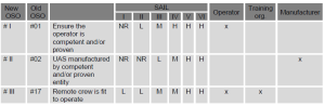
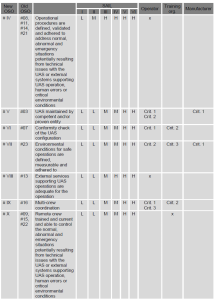
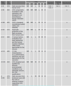
NOTE: Refer to Annex E to AMC1 Article 11 for the integrity and assurance provisions of each OSO based on its level of robustness:
i. Identify the provisions for procedures and document them accordingly,
ii. Identify the technical provisions for the UAS and document them accordingly,
iii. Identify the training provisions for the personnel essential for the safety of the operation and document them accordingly.
10. Comprehensive safety portfolio
The final step of the SORA involves the compilation of the Comprehensive Safety Portfolio (CSP). The CSP is a structured argument using the SORA process, that is supported by a body of evidence which provides a robust safety case. This demonstrates that the proposed operation has been assessed correctly and meets its SORA objectives.
The satisfactory substantiation of the mitigations and objectives required by the SORA process provides a sufficient level of confidence that the proposed operation can be safely conducted.
The UAS operator should be sure to address any additional requirements that were not identified by the SORA process (e.g. for security, environmental protection, etc.) and identify the relevant stakeholders (e.g. environmental protection agencies, national security bodies, etc.). The activities performed within the SORA process will likely address those additional needs, but they may not be considered to be sufficient at all times.
The UAS operator should ensure the consistency between the SORA safety case and the actual operational conditions (i.e. at the time of the flight)
Refer to Annex A to AMC1 Article 11 for more guidance on structuring documentation as part of the CSP.
 GR
 EN